Diode And Gate Circuit Diagram
Diagram circuit clamp gate diode output has seekic shown follow Using logic diodes gates circuit gate transistors Gate diode
Diode AND gate electron flow - Electrical Engineering Stack Exchange
Circuit diagram diode zener clamping gate seekic shown Diode as a gate tutorial and circuits Logic gates circuit
Diode or gate circuit
Diodes logic diode circuit gate 12v led voltage control 5v using input schematic sparkfun output gates resistor ics some addAnd gate: what is it? (working principle & circuit diagram) Gate circuit diagram diode diodes electrical4u 5v apply principle working above firstWorking of or gate using diode.
Diode switching circuitsGate diode circuit And gate: what is it? (working principle & circuit diagram)Diode and gate circuit.

The diode and gate
Logic gate gates diode circuit using diodes input diagram voltageElectron diode Or gate: what is it? (working principle & circuit diagram)Diode logic.
Digital logicLogic gates using diodes and transistors Circuit gate diode breadboard led build power 5vExplain logic or gate and its operation with truth table.

Diodes using gates gate diode logic resistor electronic transistors different why electronics make
Gate circuit diagram diode electrical4u diodes principle workingDiode and gate decoding circuit (one) schematic Circuit diode decoding gate schematic seekic basic diagram shown followGate diode circuit engineersgarage.
What are logic gates? or, and, not logic gate with truth tableDiode gate circuit using schematic logic circuitlab created Diode and gate electron flowWhat are logic gates? or, and, not logic gate with truth table.

Diode logic gates
Introduction to and gateDiode and gate decoder circuit (2) Gate logic circuit diode using gates diodes two voltage figureDiodes using gates logic gate circuit transistors output inputs fever.
Gate diode electronic tutorial reject signal shuts remainder opens let then through partGate diodes logic truth table explain using operation its fig Diode switching circuits gateLogic gates using diodes and transistors.

Output has a clamp diode gate circuit diagram
Circuit diode decoder gate seekic basic diagramGate circuit diode diagram using two electrical4u inputs principle working follows realized simple Circuit diode logic gates electronics resistorCircuit diode gate seekic.
Diode and gate (w subtitles)Gate circuit diode negative seekic logic positive used called asthe How to build a diode or gate circuit.

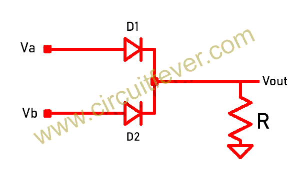
Logic Gates Using Diodes and Transistors - Circuit Fever

AND Gate: What is it? (Working Principle & Circuit Diagram) | Electrical4U

Diode AND Gate (w subtitles) - YouTube

THE DIODE AND GATE

Diode AND gate decoder circuit (2) - Basic_Circuit - Circuit Diagram

Working of OR Gate Using Diode

Diode AND gate electron flow - Electrical Engineering Stack Exchange